Wiring diagram for DNaT and MGL lamps
Unlike incandescent lamps, DNat lamps cannot be connected directly to the network. For ignition and normal operation of sodium lamps (as for any gas-discharge lamps), special starting control equipment is required.
The starting control equipment (PRA) for sodium lamps is a bundle of devices: a ballast - a choke and an IZU - a pulse ignition device. The first is necessary for starting and limiting the discharge current to the value required for normal operation of the lamps, the second, which is easy to understand from its name, serves to create a high-voltage voltage pulse that creates a discharge in the gas mixture of the DNaT bulb (actually, ignition of the lamp).
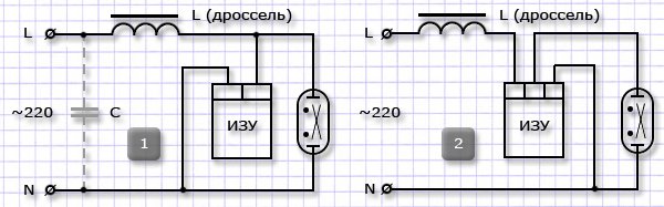
The differences between the proposed below DNaT connection schemes consist in the use of different types of ignition devices: two or more, a three-contact device is preferable.
As can be seen from the diagrams, the choke is connected to the sodium lamp power supply circuit in series, and the igniter is connected in parallel. To ensure normal operation of the lamp and its serviceability during the declared service life, the choke power must necessarily correspond to the consumed power of the DNaT.
The circuit may include a compensating capacitor connected in parallel to the power source (circuit with compensating ballast). The capacitor C shown by the dotted line in the first circuit serves to compensate for the inductive component of the circuit - reducing unnecessary consumption of reactive power, reducing the overall consumption of the operational amplifier's electricity, and increasing the service life of the lamps.
The required capacity can be obtained by using several capacitors connected in parallel.
The capacity of the capacitor(s) may be slightly larger than recommended. However, if its value is increased excessively, such a negative effect as lamp “flickering” may occur due to the occurrence of resonance in the circuit.
When assembling the circuit, special attention should be paid to the location of the control gear relative to the lamp. The control gear should be located as close as possible to the lamp base; the length of the connecting wires in this area should be minimal.
The maximum length of wires in the mentioned section recommended by some manufacturers of these devices is up to 1-1.5 m. Special high-voltage wires should be used for connections.